E-Portfolio
building information modelling
Project 2b Building Documentation - Work In Progress
WIP. Work In Progress
Topography . Site Components
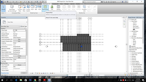

Go to >massing & site > toposurface > place point to create contour.

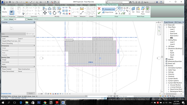
To cut hole for the building, go to > Building Pad> draw out the building boundary.

Go to Site Component to put trees.

Room Tag
Type command "RM" to label the room spaces

Spaces that is not enclosed is not detectable by room tag, > Room Seperator" draw the boundary and insert room tag.

Double click on the room and rename it. Go to Properties Type and check the show area.

>Tag by category to tag the type of doors and windows

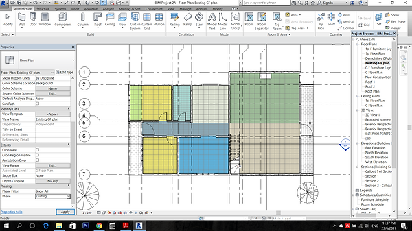
To label the spaces with colour scheme, >Annotate > Color Fill Legend

Choose "Room" for the space type and "Name" for colour scheme
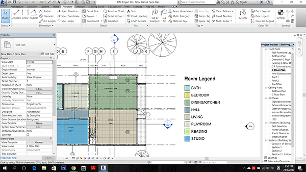
The colour filled legend is done. Repeat the same step for the First Floor Plan.
Room Schedule
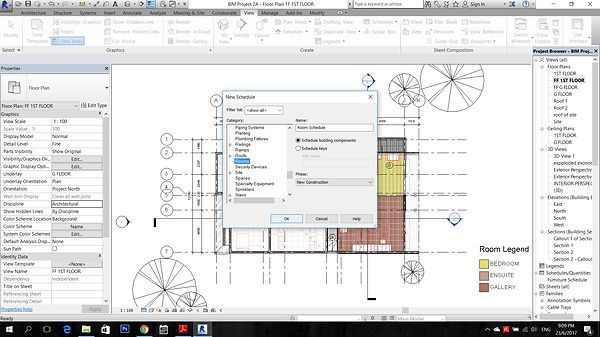
Go to "Analyse" > Schedule/Quantities> select Room category

For the schedule Properties > add Name, Area and Level > ok

Then the Room Schedule is done.
Furniture Layout Plan
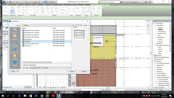
Duplicate the floor plans to for placement of furniture. >Architecture >Components >Place a component >Load Family to place the furniture, Plumbing and specialty equipment.

On the duplicated ground floor plan and first floor plan, unchecked the boxes of furniture, plumbing and specialty equipment from the "visibility" setting tab.

Go to >View >Filter >create a new filter name Furniture Layout >ok

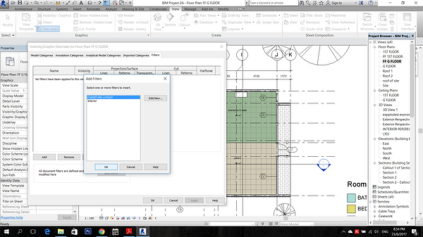
For the categories, Check the boxes of furniture, plumbing fixtures and specialty equipment >ok
>View >Visibility >Filters >add Furniture layout

Colour is selected to change the outline of the furniture placed.

The furniture layout plan is done.
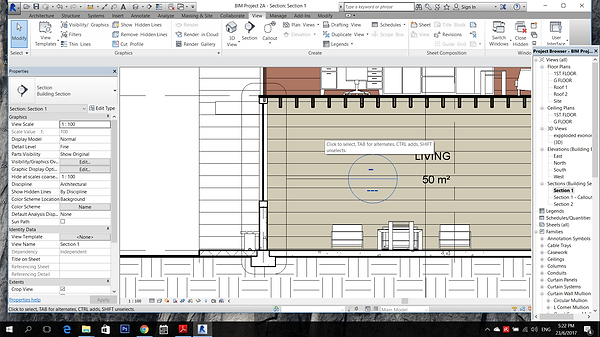
Sections

To cut a section, go to View> draw a section cut
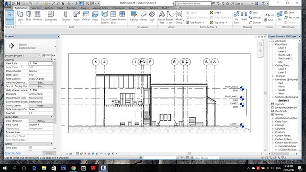
A section view is formed

To add room tag to the spaces, >Annotate >Room tag

Repeat the same steps to create the colour fill legend for sections.

On the sections created, masking region is selected from the region tab to allow masking over the section.

Pad footings were drawn using line under the masking region. Masking region is usually used to add detailing on the section without changing the original.

The lineweight can be change from the Line Style.

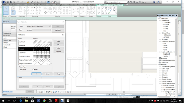
Go to Properties Type, concrete materials pattern can be added.
Callout of sections
Go to View tab > Callout> draw on the part that its details are wished to be shown. Then the View of the callout is created at the project browser.
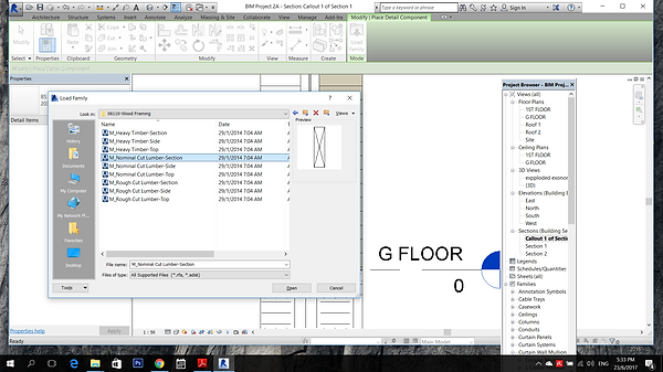

The detailing can be load from the library, >Annotate >Component> Details Component> Load family

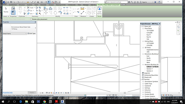
The Pad footing is drawn on the masking region.

Anchor Bolt is loaded from library and placed to connect to the footing.
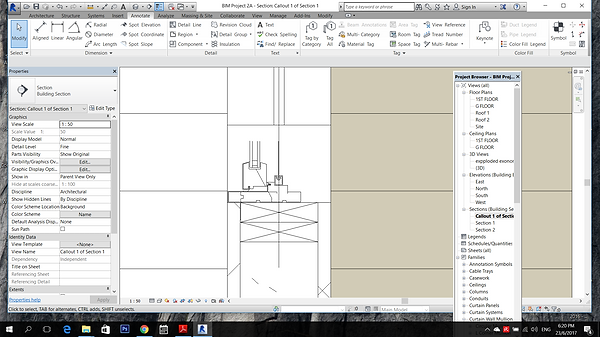

The second callout is created by repeating the same steps as the callout 1.
Exploded Isometric

Duplicate the 3D view for exploded isometric.

Select the components according to level >View tab> Displace Element

After all the components is exploded according to levels, select Path to draw the dotted path.
Exterior and Interior Perspective


To create perspective view, "Camera" is selected from the view tab and placed on the plan for perspective viewing.
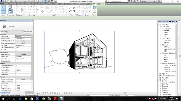
A new "3D" perspective view will appear under the 3D tab at the project browser.

To cast shadow to the perspective view, Click the Visual Style at the bottom >Graphic display option >Shadows>check the box of the cast shadow.
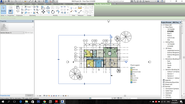
For Interior Perspective, the view can be controlled by checking the "section box" to allow changes on the sectional perspective view by adjusting the blue outlined box.

The blue outlined box is the crop region view while the black outlined box is actually the section box. View can be adjusted by moving around the section box or crop region box.
Phasing
The plan selected is duplicated for three times for different stages, Existing, Demolished and New Construction.
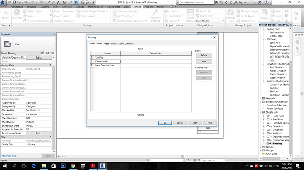
Three project phases are created including existing, demolished and new construction on the Project phase tab

The phase filters setting is as above.

The graphic overrides setting are as above.

On the original ground floor plan, all the components are selected and changed to existing for the phasing.

On the "Existing" plan for phasing, at the phasing filter set to "Show All" and phase is changed to "Existing"
On the "Demolished", the phasing filter set to "Show Complete" and phase is changed to "Demolish"

On the existing phase, select the component that is to be demolished and change the phase to demolished.

On the new construction phase, new "wall" component is added.

The selected demolished component will be in blue dotted outline.


Repeat the same steps for the 3D views.
Plot

To place all the drawings on the sheet, first is select the new sheet created under the "Sheet" tab and drag the drawings wanted to the sheet and place it.
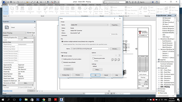
After complete plotting all the drawings into the sheets, > print >save in PDF>ok